How To Identify PCI Express Vs PCI Expansion Slot?
PCI, Peripheral Component Interconnect, is a form of internal data bus for connecting or injecting peripheral devices into a computer. In 1990, Intel introduced the PCI standard and by 1995 it was popularly implemented in computers. Today, PCI and its variants’ specifications are managed by the PCI-SIG (PCI Special Interest Group), a combination of financial institutions of over 900 companies.
PCI is a general-purpose connection standard designed to support multiple devices of various kinds, including graphics hardware, audio hardware, network hardware, and such. Alterations of the PCI standard have boosted new features and performance improvements, including different bus speeds and bus widths. Different potential bandwidths for the most popular variants of the basic PCI standard are as follow: 32 bits with 33 MHz have potential bandwidth of 133 MB/s, 32 bits with 66 MHz have potential bandwidth of 266 MB/s, and 64 bits with 66 MHz have potential bandwidth of 532 MB/s. These assorted types of slots and expansion cards are ordinarily harmonious with each other. If a card and slot are designed to accept a wider bus or a faster bus speed, then it would typically default to a lower setting.
PCIe, PCI Express, introduced lately as a standard for connecting devices to computers. The software is compatible with PCI but has greater potential bandwidth and larger flexibility than PCI. PCI-SIG manages the PCIe specification as well. Because the two standards share a mutual foundation, majority of the new computers support PCIe and PCI for more compatibility. PCIe is used for internal Wi-Fi cards, 10 Gigabit Ethernet cards, hard drives, and Solid State Drives (SSDs).
A “link” refers to as a connection between a PCIe device and the system. The link is constructed around a dedicated, bi-directional, serial (1-but), point-to-point connection called a “lane”. A lane is able to simultaneously transfer 250 MS/s of data in each direction. A link can use more than one lane at a time by all links compliant with the PCIe specification must minimally support single-lane connections, known as “x1”links.
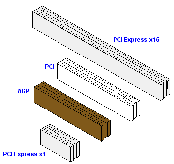
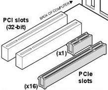
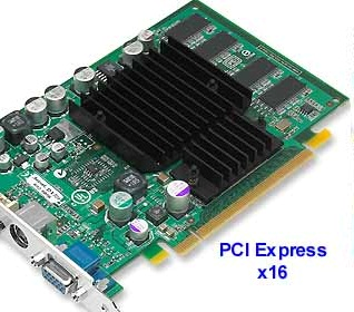
For greater potential bandwidth, PCIe devices and systems have the option to support links using multiple simultaneous lanes- for example; a “x16” link uses 16 lanes. To be able to support the extra lanes, a PCIe card and slot have to be designed to coordinate the extra electrical lines required which is 2 lines per lane. Card and slot types for x1, x4, x8, and x16 links are available. At present, graphic cards are the only devices that use a x16 link. Other devices generally don’t obligate the high potential bandwidths provided by such a connection.
PCIe cards can physically fit into slots that are designed for their lane configuration or higher (up-plugging) but will not fit into slots designed for lower lane configurations (down-plugging). For instance, a x1 card will fit into x1, x4, x8, and x16 but a x16 card will only fit into a x16 slot. A x1 card in any compliant PCIe slot will always run in x1 mode.
The internal structural design of PCIe is a lot like a local area network in that each link goes a central hub in the computer that performs network-like switching. This is a contrast to the PCI architecture whereas all devices share the same unidirectional, parallel bus. Because PCIe isn’t based on parallel connections that can be hindered by timing issues, PCIe allows data to be more easily and cost-effectively transmitted over longer distances. The PCI-SIG is developing a cabling specification to allow external devices to be connected to a computer using the PCIe standard.